An AES standard which defines the use and pin-outs of 25-pin D-sub connectors for eight-channel balanced analogue audio travelling in a single direction in or out of a device, and an alternative bi-directional eight-channel digital interfacing (four AES3 threes in each direction). It conforms fully with the established Tascam interface standard.
AES59 Multichannel Analogue Digital D‑sub Connections
In applications involving multiple audio channels, such as console, interface, or recorder connections, individual cables can become expensive, bulky, and inconvenient. In these situations a multi-pole connector is generally preferred, allowing the connection (and disconnection) of a large number of channels with a single plug and cable. Many different multi-pole audio connector standards have evolved over the years for different applications, but one which has become genuinely ubiquitous was devised by Tascam in the early 1990s as a proprietary means of interfacing its range of 8-track DA-nn digital tape recorders.
Tascam chose to use ITT-Cannon’s ‘D‑subminiature’ connector for this purpose since it had well-proven reliability in the computer industry, was moderately cheap, and readily available. It was also a convenient size, had a shielded shell, was relatively easy to wire up, and could be secured in place with thumbscrews (using 4/40 UNC screws, not the incompatible M3 threads found on some D‑sub connector variants).
ITT-Cannon’s D‑sub connector is available in various configurations from 9 to 50 pins, but Tascam chose the 25‑pin variant as the ideal means of conveying eight balanced analogue or AES3 digital audio circuits. Female connectors are always used on the equipment (regardless of whether the socket is carrying inputs or outputs), and male connectors are used on the cables. This arrangement was chosen because female connectors are much less likely to suffer mechanical damage and equipment-mounted connectors are difficult to replace — so it makes sense to use the female sockets on the equipment. If a cable plug suffers bent pins an alternative cable can be substituted, or it can be replaced relatively easily.
Analogue Interfacing
Such was the practicality and convenience of Tascam’s D‑sub format that many other manufacturers quickly embraced it for eight-channel analogue interconnections on their equipment too. This ubiquity was finally recognised by the AES in 2012 when the format was ratified as the AES59 standard (AES standard for professional audio — audio application of 25-way D-type connectors in balanced circuits). The wiring arrangement is detailed in the table and diagram below:
While the pin assignments may appear to be random in the table, the diagram makes clear the very logical physical arrangement of individual balance signals across the plug. It’s worth noting that each separate balanced signal has its own independent earth connection (an important consideration for phantom powered microphone applications), and only one pin remains unused. When used for analogue signals this Tascam/AES59 wiring protocol requires that all eight balanced signals travel in the same direction, so a plug can carry eight analogue inputs or eight analogue outputs, but never both inputs and outputs on the same cable.
Some commercially-made D‑sub cables are equipped with XLRs at the break-out end, which obviously defines the direction of signal flow (male XLRs for outputs, female XLRs for inputs), but break-out cables equipped with TRS plugs can be used for input or output connections. It is also worth stating that while the Tascam/AES59 interface is most commonly used for balanced line-level signals, it is also often used for conveying balanced mic-level signals (with or without phantom power).
AES59 Multichannel Digital D‑sub Connections
In the dawning years of compact multichannel digital audio recorders and mixers, every manufacturer defined its own connection protocols. Although most adopted the same physical 25‑pin D‑sub connector for conveying eight channels of digital audio, a variety of bespoke and completely incompatible wiring conventions evolved — much to everyone’s frustration. This approach made it very difficult to connect together equipment from different manufacturers, but common sense gradually prevailed and most manufacturers eventually embraced Tascam’s wiring format again carrying AES3 signals. This was ratified as the AES59 standard in 2012, and uses ITT-Cannon’s 25‑pin D‑sub connector (using 4/40 UNC securing screws, not the incompatible M3 threads found on some D‑sub variants).
Female connectors are always used on the equipment (regardless of whether the socket is carrying inputs or outputs), and male connectors are used on cables — the reason being that female connectors are much less likely to suffer mechanical damage and equipment-mounted connectors are difficult to replace, so it makes sense to use the female sockets on the equipment.
So, the AES59 standard not only dictates the interface’s use with eight channels of balanced analogue audio, it also specifies its use for digital audio applications as well, and the vast majority of manufacturers have already embraced the AES59 standard for multi-channel digital audio. The only significant exception today is Yamaha which uses the same physical 25‑pin D‑sub but with a bespoke wiring arrangement for its AES3 interfaces (see below).
The AES59 connection standard states that it can be used with digital equipment in exactly the same way as for analogue (if required), passing eight separate AES3 balanced digital inputs or outputs in one direction only. Since AES3 data streams normally carry two interleaved audio channels this configuration obviously caters for up to 16 separate digital audio channels via a single 25‑pin D‑sub connector.
However, this unidirectional configuration is rarely employed, and most digital D‑sub interfaces convey four AES3 inputs alongside four AES3 outputs, providing eight input and eight outputs channels via the one D‑sub connector. The AES calls this arrangement a ‘digital combined I/O’ mode, and the standard requires that the first four channels are used as AES3 inputs, while the last four provide AES3 outputs. This configuration is shown in the table and illustration below:
Tascam, AVID, Digidesign, Universal Audio, RME, Focusrite, and SADiE (amongst many others) all employ this AES59 wiring convention, and other manufacturers are likely to adopt it as new equipment is introduced.
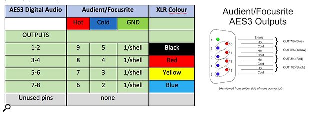
However, for multichannel A-D converters which only have outputs, an alternative arrangement exists using a smaller 9‑pin D‑sub connector. Audient and Focusrite both employ this format on their eight-channel mic preamps, for example.
Yamaha YGDAI
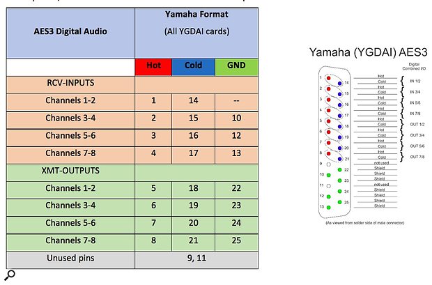
As I mentioned previously, Yamaha maintains their bespoke AES3 interface format, and this is used on all of the company’s YGDAI and mini-YGDAI interface cards, as well as on some legacy Apogee, Akai, Mackie, Lynx, and SSL equipment (amongst others).
The table and diagram below illustrates this Yamaha format which, although conveying four AES3 inputs and four outputs, has entirely different and incompatible wiring within the D‑sub connector itself. If Yamaha and AES59-compatible equipment are connected together with a standard AES59 cable, a few channels will actually work, but with reversed directions different channel pairs!
Where it is necessary to interconnect Yamaha and AES59 equipment, a proper conversion cable is required (Alva-Audio offer appropriate adapter cables, for example). Alternatively, RME manufacture a rack-mount break-out connection panel called the BOB32 which can be configured to connect between both AES59 and Yamaha D‑sub formats.
Legacy Digital Wiring Formats
For the sake of completeness, before the audio industry coalesced to the AES59 format, several other incompatible formats were in use. The table below details three of the most common arrangements which may still be encountered if working with legacy equipment.
Note that the Tascam TDIF interface does not carry AES3-compatible data, so even if a cable was wired according to this table it would not be possible to exchange audio data between a TDIF device and a unit passing AES3 data.
Note: Although the Genex wiring arrangement uses the same pin groupings as the AES59 format, the input and output directions (as well as the channel orders) are reversed. Some older legacy Digidesign equipment employs the same arrangement.


